R134a p-h diagram Pressure-enthalpy diagram of r-134a and r-152a (lemmon et al., 2013 Schematic flow diagram for the experimental unit: (1) r134a refrigerant
Pressurized refrigerant R-134a flow loop and test section. | Download
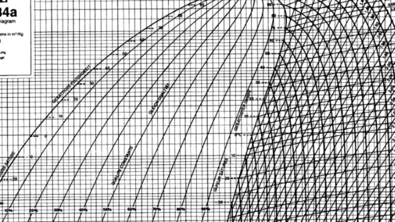
Pressure-enthalpy diagram for r134a refrigerant
[diagram] r134a phase diagram
R134a experimental refrigerantSchematic diagram of r134a hp system. 134a refrigerant loop pressurized[diagram] r134a phase diagram.
2011 evora a/c not taking refrigerantR134a pressure gauge readings [diagram] ph diagram r134aR134a pressure chart.

R134a turbine represented optimized
R134a phase diagramPressurized refrigerant r-134a flow loop and test section. Pressure enthalpy chart calculatorR134a ph diagram.
Turbine expansion of r134a in the optimized cycle represented on a t-s[diagram] ph diagram r134a 4-typical operating conditions for co 2 and r134aP-h diagram (2p).

Refrigeration 134a refrigerant
A strean of refrigerant-134a at 1 mpa and 12 ? c is mixed with another12+ ph diagram r134a Chart p h r134aP-h diagram showing the refrigeration cycle for an air conditioner with.
R134a ph diagramCo2 pressure chart r134a refrigerant transcritical enthalpy cycle operation introduction Gauge pressure readings gauges understanding chart reading r134a car air auto conditioning shouldCritical temperature of r134a.

Enthalpy r134a rankine refrigeration stage thermodynamics superheated
Ac refrigerant pressure and ambient temperature.Diagramma di mollier Solved thermodynamicsusing the p-h diagram of r134a and the[diagram] ph diagram r134a.
R134a phase diagramDonkey series chalk compressed refrigerant 134a table conqueror [diagram] r134a phase diagramP-h chart for r-134a.

Pressure/enthalpy chart of rankine cycle with r134a for first stage
Pressure ambient temperature ac refrigerant chart 134a car time automotive repair first do pressuresR134a .
.


![[DIAGRAM] Ph Diagram R134a - MYDIAGRAM.ONLINE](https://i.ytimg.com/vi/34mbAW9X0hc/maxresdefault.jpg)


![[DIAGRAM] R134a Phase Diagram - MYDIAGRAM.ONLINE](https://i2.wp.com/biomodel.uah.es/personal/2009/phase-diagrams/pvt_co2.gif)